3D/2D Plant Design
TNI builds integrated 3D plant models and produces 2D drawings for piping systems, skid packages and steel structures in AutoCAD Plant 3D and Navisworks Manage. Fabrication drawings, isometrics and material take-off (MTO) are extracted directly from the model, so they always stay consistent.
Design scope
| Phase | Deliverables |
|---|---|
| Basic design | Plot plan, equipment GA layout, preliminary main pipe routing |
| FEED & 3D modeling | Piping routing, skids/modules, steel structures (platforms, stairs, handrails), pipe supports, cable trays |
| Detail design | Piping arrangement, skid assembly, face piping, frame detail, support detail, structure shop drawings |
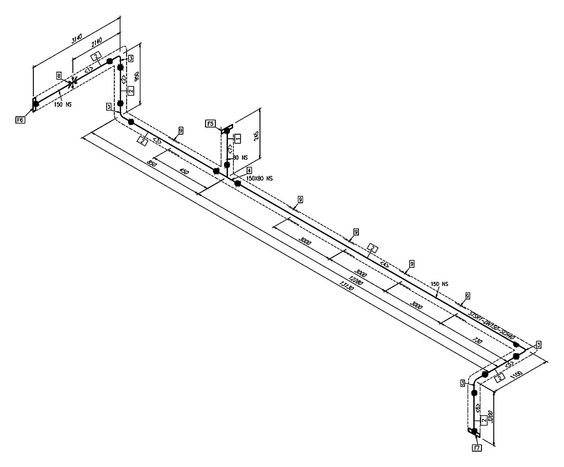
| Isometrics | Line-by-line isometrics with bill of materials, weld numbers and cut lengths |
| MTO | Pipes, valves, fittings, flanges, bolts and gaskets by line, area or system |
Workflow
- Receive P&IDs, equipment datasheets, plot plan, piping classes and project specifications.
- Build the Plant 3D spec library for each piping class (ASME B36.10M/B36.19M, ASME B16.5, JIS, DIN, etc.).
- Model equipment and structures and route piping with access, maintenance and removal clearances.
- Run clash detection and review the model with the client in Navisworks.
- Issue GA, isometric, support drawings and MTO; revise to comments until approval.
- Hand over native files (DWG, model) and as-built drawings when required.
Input we need from you
- P&IDs and line list.
- Equipment datasheets or outline drawings with nozzle positions and orientations.
- Building layout, elevations and existing structures.
- Piping classes / materials and flange and fitting standards.
- Special requirements: drainage slopes, insulation, hygienic piping, maintenance clearances.
Benefits of 3D design
- Less rework on site: clashes between piping, structures and cable trays are found during design.
- Realistic MTO: quantities taken from the model support procurement and cost control.
- Consistent drawings: change the model and GA, isometrics and MTO update together.
- Faster approval: owners review an intuitive 3D model rather than 2D drawings only.
Fabricator’s perspective
Our designers think like fabricators: spools are split to suit transport and pickling, field welds are placed where they are easy to execute, and pipe lengths are planned around standard 6 m random lengths to reduce waste.
Selected design work
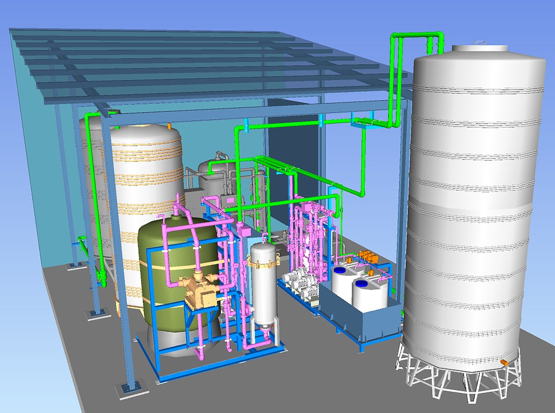
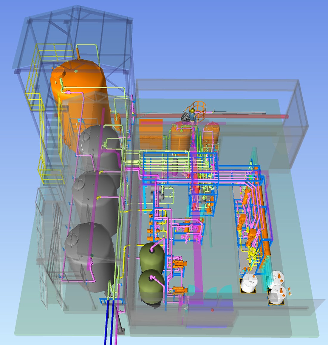
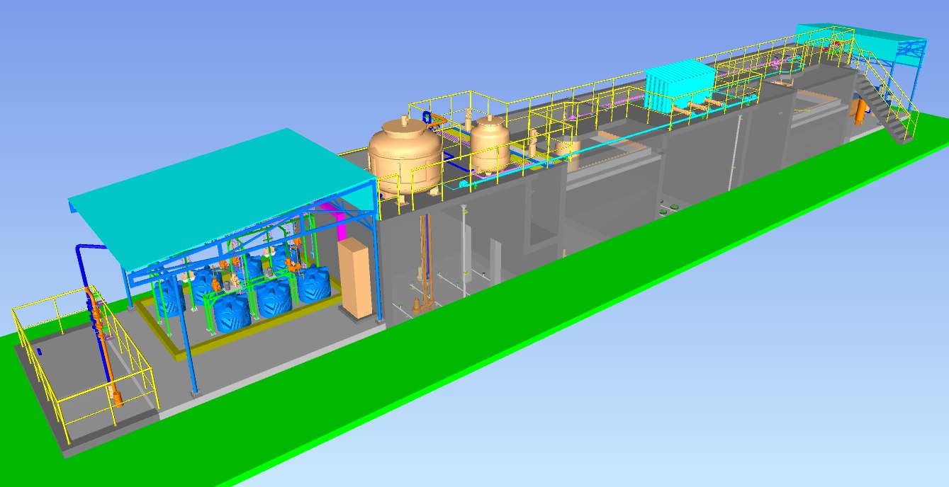
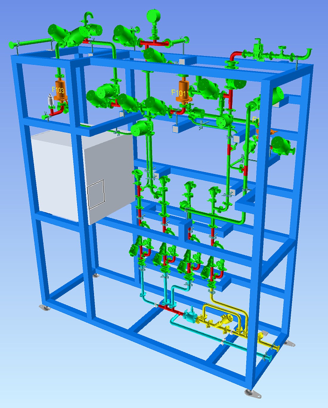
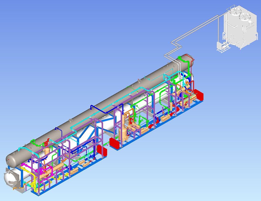
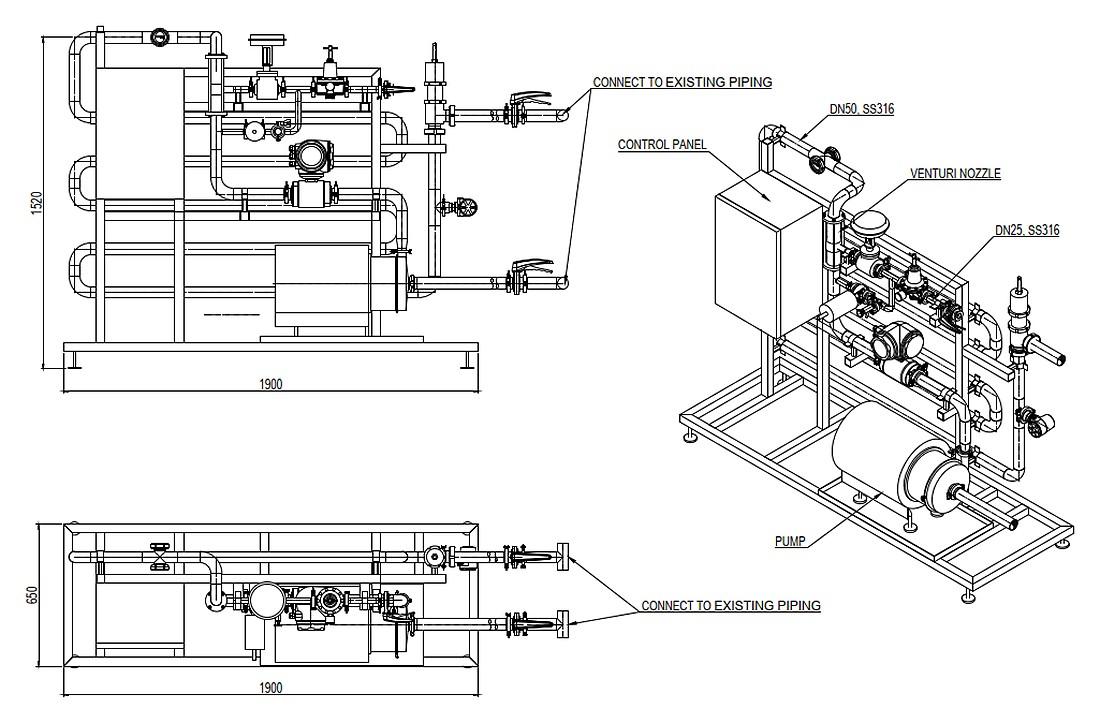
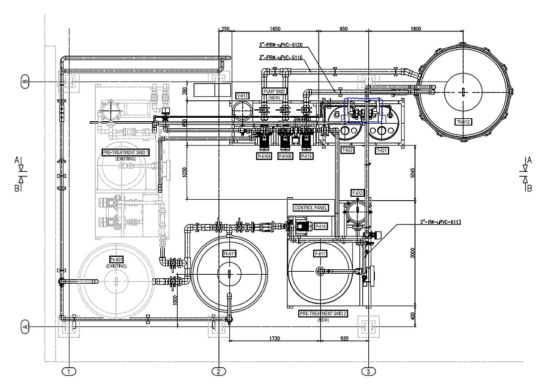
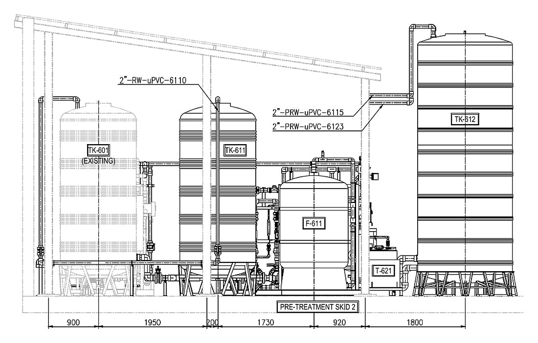
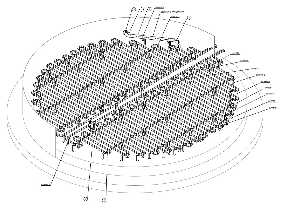
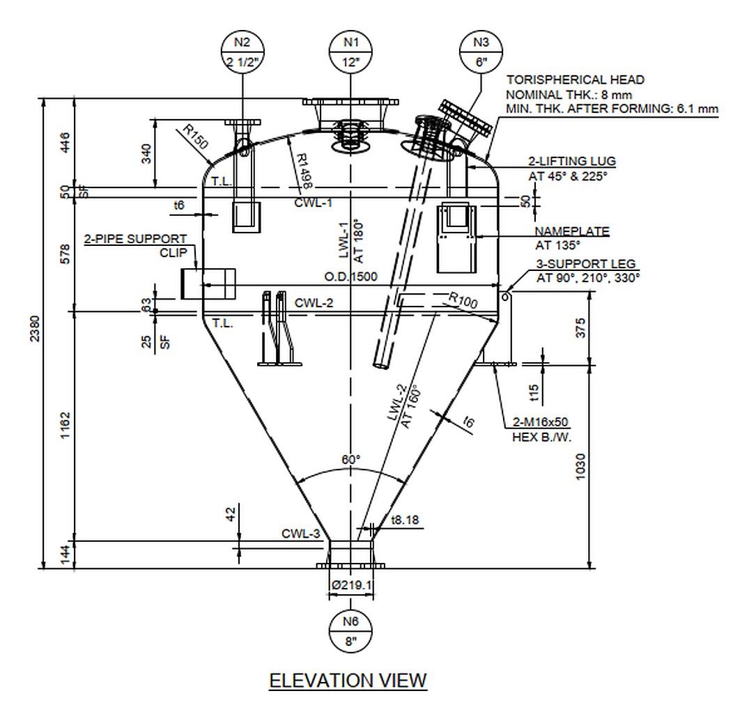
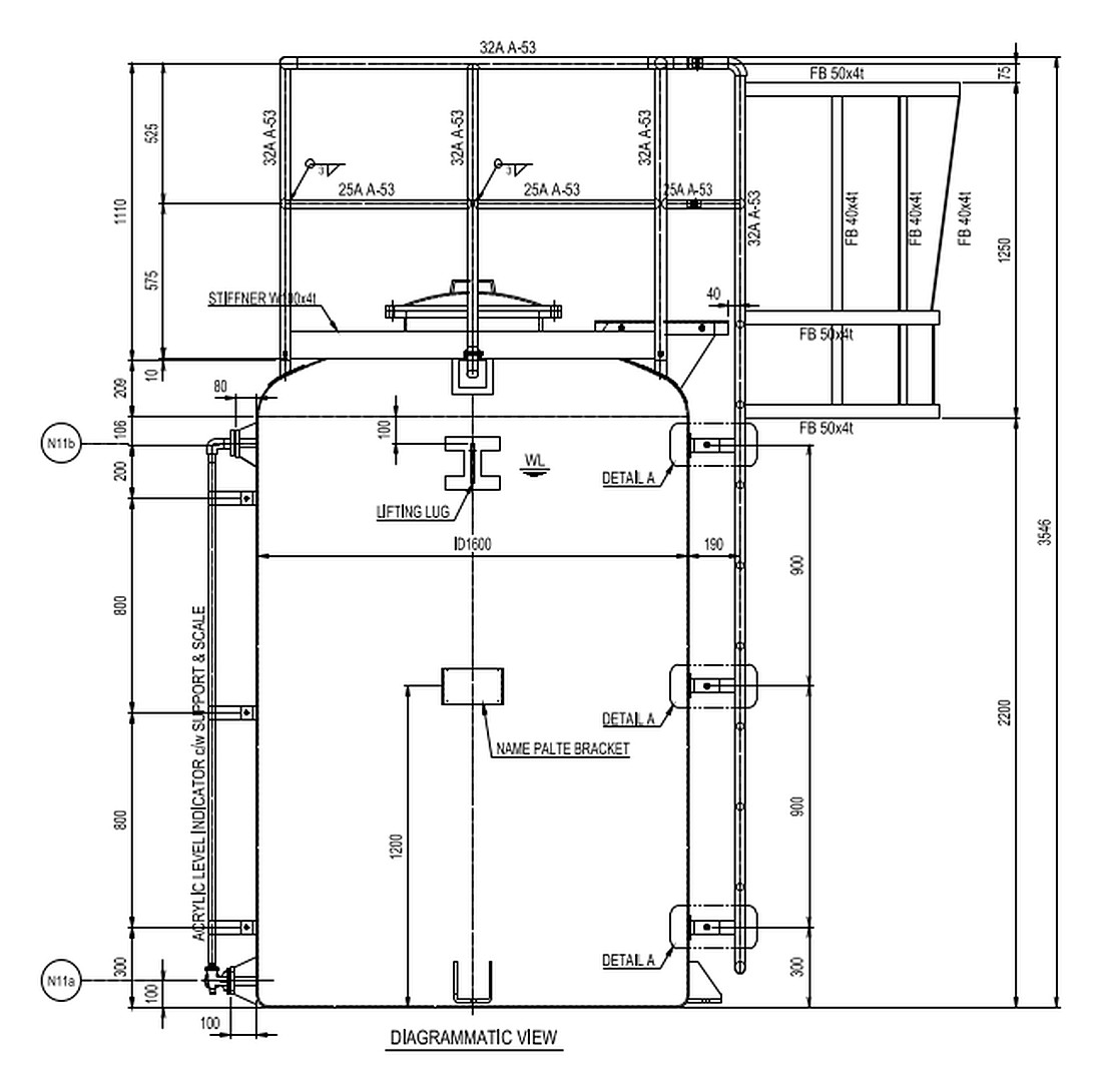
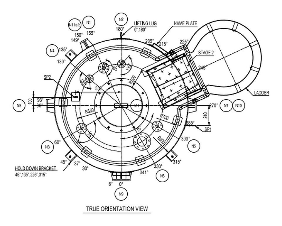
Selected 3D models and 2D drawings produced by the TNI team. Client information and design data have been removed in line with our confidentiality commitments. Click an image to enlarge.
3D models

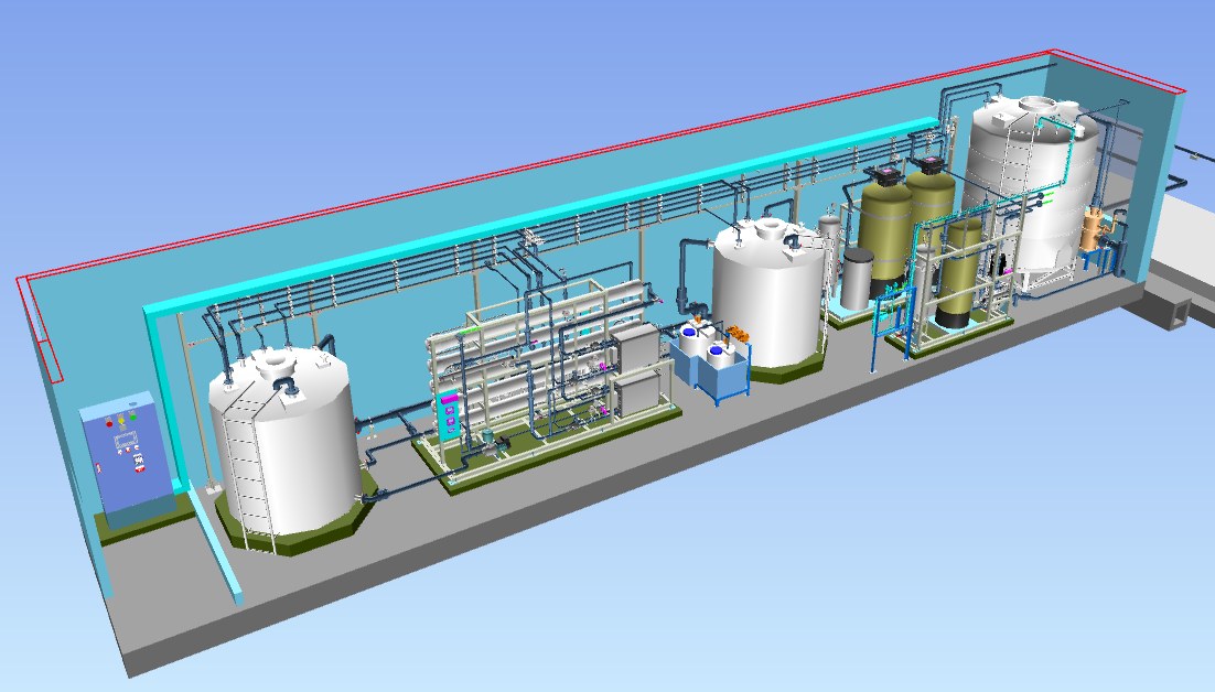

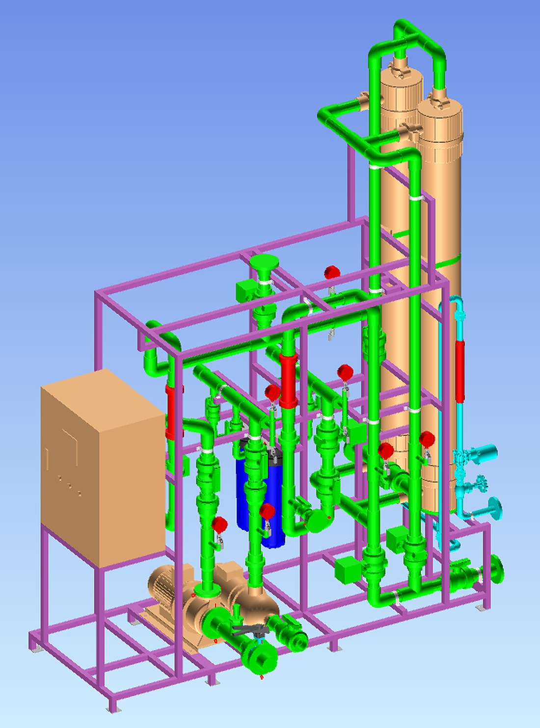
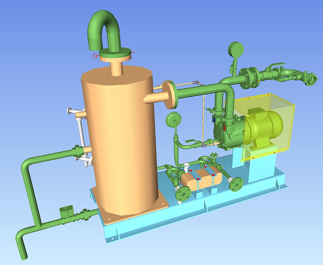
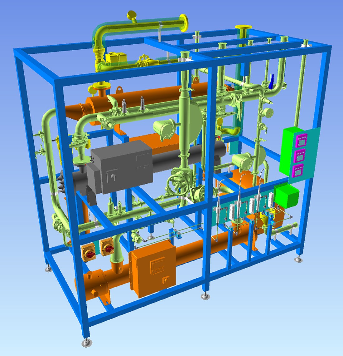
2D drawings
Reference projects
- 3D piping models, isometrics and stress analysis for sites in Australia and New Zealand.
- GA layouts and piping for multiple water and wastewater treatment systems.
- UF, compressed air and chemical dosing skid design for Japanese and FDI clients.
Related services: Piping stress analysis · Tank & pressure vessel design · Skid & equipment fabrication
Need a 3D model and drawings for your project?
Send your P&ID, drawings or datasheets – a TNI engineer will reply within 24 hours.