Flange Pressure Ratings: ASME Class, JIS K and EN/DIN PN
When ordering flanges, the most important parameter after size and material is the pressure rating. The three standard systems common in Vietnam use three different designations: Class (ASME), K (JIS) and PN (EN/DIN). This article explains what each designation means, how to read the allowable working pressure at temperature, and why flanges from different systems cannot be mixed.
Part of our piping series: Industrial piping classification · Pipe fittings and connection types.
What is a flange pressure rating?
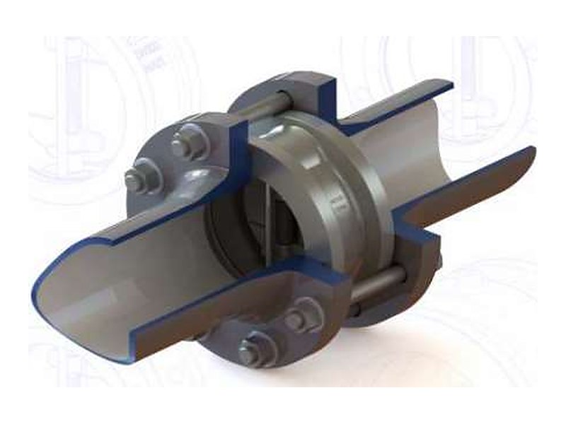
It is a designation that identifies the pressure level a flange is designed for. The rating determines the flange thickness, bolt circle diameter and the number and size of bolts. The actual allowable working pressure also depends on material and temperature, and is not always equal to the number in the designation.
1. Overview of the three systems
| Standard | Rating designation | Common ratings | Nominal sizes | Typical market |
|---|---|---|---|---|
| ASME B16.5 (USA) | Class | 150, 300, 400, 600, 900, 1500, 2500 | NPS ½ – 24 (larger: ASME B16.47) | Oil and gas, chemicals, US equipment, international projects |
| JIS B2220 (Japan) | K | 5K, 10K, 16K, 20K, 30K, 40K, 63K | 10A and up (A sizes in mm) | Japanese projects and equipment, water treatment |
| EN 1092-1 (Europe, supersedes DIN) | PN | PN6, 10, 16, 25, 40, 63, 100… | DN10 – DN4000 (depending on PN) | European equipment, valves, pumps, water supply and drainage |
- Class (ASME): only an identifying number, not a pressure. A carbon steel Class 150 flange is rated about 19.6 bar (285 psi) at ambient temperature, not 150 psi.
- K (JIS): approximately the maximum working pressure in kgf/cm² at ambient temperature. 10K ≈ 10 kgf/cm² ≈ 9.8 bar.
- PN (EN/DIN): nominal pressure in bar at the reference temperature. PN16 ≈ 16 bar; as temperature rises, the allowable pressure decreases according to the material group.
2. Working pressure decreases as temperature rises
Each standard has pressure–temperature (P–T) rating tables for each material group. The chart below shows carbon steel flanges (group 1.1, e.g. ASTM A105) per ASME B16.5: the higher the temperature, the lower the allowable pressure.
| Temperature (°C) | Class 150 | Class 300 | Class 600 | Class 900 |
|---|---|---|---|---|
| −29 to 38 | 19.6 | 51.1 | 102.1 | 153.2 |
| 100 | 17.7 | 46.6 | 93.2 | 139.8 |
| 150 | 15.8 | 45.1 | 90.2 | 135.2 |
| 200 | 13.8 | 43.8 | 87.6 | 131.4 |
| 250 | 12.1 | 41.9 | 83.9 | 125.8 |
| 300 | 10.2 | 39.8 | 79.6 | 119.5 |
| 400 | 6.5 | 34.7 | 69.4 | 104.2 |
Stainless steel has different values: a Class 150 flange in 304 or 316 is rated only about 19.0 bar at ambient temperature, slightly lower than carbon steel.
| Temperature (°C) | 10K | 16K | 20K | 30K |
|---|---|---|---|---|
| up to 120 | 14 | 27 | 34 | 51 |
| 220 | 12 | 25 | 31 | 46 |
| 300 | 10 | 23 | 29 | 43 |
| 350 | – | 21 | 26 | 39 |
A carbon steel JIS 10K flange allows about 14 bar (1.4 MPa) up to 120 °C, higher than the “10” in its designation. Even so, TNI always selects ratings from the pressure–temperature table of the specific material, never from the designation alone.
3. Why flanges from different systems do not fit together
For the same 100 mm pipe size and a comparable rating, the three standards have different outside diameters, bolt circle diameters (PCD) and bolt sizes. A difference of a few millimetres is enough to stop the bolts from passing through.
| Pipe size | ASME B16.5 Class 150 | JIS B2220 10K | EN 1092-1 PN16 |
|---|---|---|---|
| 50 mm (NPS 2 / 50A / DN50) | OD 152.4 · PCD 120.7 · 4 × 5/8″ | OD 155 · PCD 120 · 4 × M16 | OD 165 · PCD 125 · 4 × M16 |
| 100 mm (NPS 4 / 100A / DN100) | OD 228.6 · PCD 190.5 · 8 × 5/8″ | OD 210 · PCD 175 · 8 × M16 | OD 220 · PCD 180 · 8 × M16 |
ASME also assigns nominal PN equivalents to each Class: Class 150 ≈ PN20, Class 300 ≈ PN50, Class 600 ≈ PN110. These are only equivalent designations; the dimensions remain ASME and do not mate with EN PN16 or PN40 flanges.
4. How to select the flange rating
- Determine the line’s design pressure and design temperature (not the operating pressure).
- Identify the flange material and its material group in the standard.
- Look up the pressure–temperature table and choose the lowest rating whose allowable pressure ≥ the design pressure at the design temperature.
- Check the system test pressure (hydrotest) and the external loads (bending moment) at the flange.
- Use one standard system for the whole line, its valves and equipment nozzles.
Example 1: Hot water, design pressure 10 bar at 150 °C, A105 flanges. Class 150 at 150 °C allows 15.8 bar ≥ 10 bar → select Class 150.
Example 2: Steam, design pressure 18 bar at 250 °C, A105 flanges. Class 150 at 250 °C allows only 12.1 bar < 18 bar → Class 300 is required (41.9 bar).
Example 3: JIS, 12 bar at 200 °C: a carbon steel 10K flange at 220 °C allows 12 bar, right at the limit → select 16K for margin.
5. Reading flange markings
- 4″ – nominal size NPS 4 (DN100)
- CL150 – pressure rating Class 150
- RF – Raised Face
- WN – Weld Neck flange
- SCH40 – hub bore matched to Schedule 40 pipe
- ASTM A105 – forged carbon steel (group 1.1)
- ASME B16.5 – dimensional and rating standard
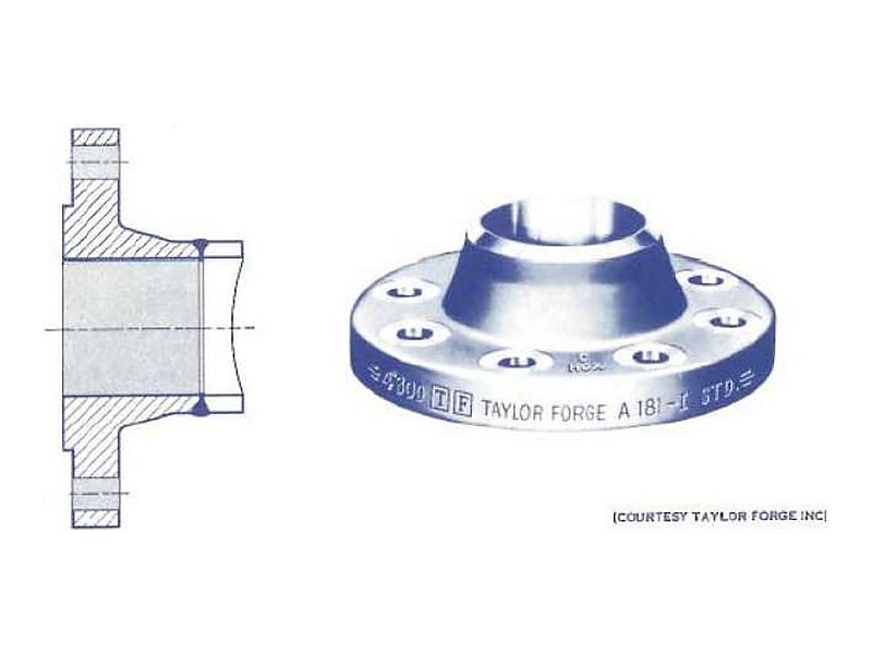
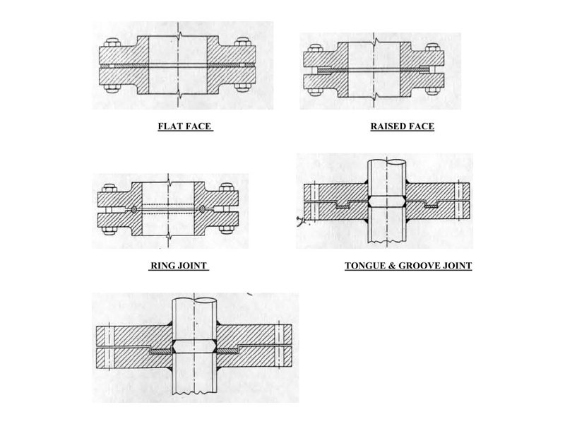
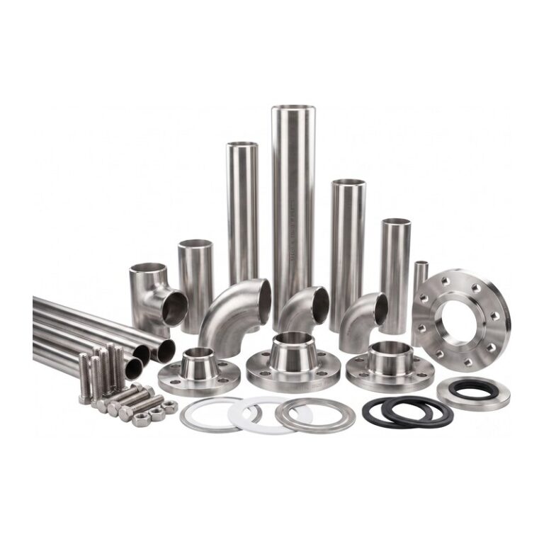
Facings must match too: flat face FF, raised face RF, ring type joint RTJ, tongue and groove, male and female. Class 150 and 300 flanges usually have RF; flanges mating with cast iron, plastic or FRP equipment use FF to avoid cracking. High-pressure flanges (Class 900 and above) usually use RTJ with metal ring gaskets.
See the flange types in Pipe fittings and connection types.
6. Practical experience from TNI
- Projects for Japanese clients usually standardise on JIS 10K. When buying US or European equipment (pumps, valves, instruments), specify flanges drilled to JIS 10K in the purchase order, or provide adapter flanges.
- ASME flanges use inch bolts; JIS and EN flanges use metric bolts. Gaskets also follow each standard, so order complete matched sets: flanges, gaskets and bolts.
- On P&IDs and isometrics, always state the standard, rating and facing (e.g. “JIS 10K FF”, “ASME CL150 RF”). Missing information here is the most common cause of wrong material orders.
- In AutoCAD Plant 3D, TNI sets up piping classes in the project’s flange system, so the generated MTO already has the correct standard, rating and bolting.
Conclusion
Class, K and PN are three different rating designations and cannot be converted directly by their numbers. To select correctly, use the pressure–temperature table of the specific material and keep one consistent standard system for the whole line.
Need help with flange ratings, design or supply?
TNI designs piping to ASME B31.3 and supplies flanges, gaskets and bolting to ASME, JIS and EN.
Quick tools: Pressure converter bar ↔ psi ↔ MPa ↔ kgf/cm² · Pipe size lookup NPS ↔ DN ↔ OD
References
- ASME B16.5 – Pipe Flanges and Flanged Fittings, NPS ½ through NPS 24 (P–T tables, material groups 1.1, 2.1, 2.3).
- ASME B16.47 – Large Diameter Steel Flanges, NPS 26 through NPS 60.
- JIS B2220 – Steel pipe flanges.
- EN 1092-1 – Flanges and their joints: Steel flanges, PN designated.
- Engineers Edge – Pressure ratings for Group 1.1 materials per ASME B16.5.
- Project Materials – Class 150 flange temperature limits; What is JIS B2220.
- Roymech – BS EN 1092-1 PN16 dimensions.